
2007-2014 Cadillac Escalade models; 2007-2013 Chevrolet Avalanche, Silverado, Suburban, Tahoe; 2007-2013 GMC Sierra and Yukon models; 2014 Chevrolet Silverado HD, Suburban, Tahoe; 2014 GMC Sierra HD and Yukon models; and 2008- 2009 Hummer H2
The Data Link Connector (DLC) allows a scan tool to communicate with the high-speed GMLAN (Local Area Network) serial data modules. The serial data is transmitted on two twisted wires that allow speeds up to 500 Kb/s. The twisted pair is terminated with two 120-ohm resistors – one is internal to the ECM and the other at the opposite end of the high-speed bus after the last module.
If a communication signal is lost, the software application will set a no communication U DTC (Diagnostic Trouble Code) against the respective control module. A loss of serial data DTC does not represent a failure of the module that the code is set in.
Always refer to the appropriate Service Information for the latest diagnostic information and procedures. The following diagnostic tips may help in locating the source of a loss of communication with a high-speed LAN module.
If the scan tool cannot communicate with any high-speed LAN modules, check for proper terminal drag at the DLC terminals 6 and 14 using test probe J-35616-14 or -2A. These terminals can become damaged from repeat probing and/or installing of the scan tool.
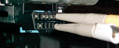
Probe terminals 6 and 14 using the proper test terminals.
Verify the high-speed LAN circuit integrity by measuring the resistance across DLC terminals 6 and 14 with a DVOM with the battery disconnected. A normal reading would be 60 ohms +/– 5 ohms. A reading less than 60 ohms would indicate the high-speed LAN bus is shorted together and a higher reading indicates high resistance/open in the high- speed LAN bus.

If the high-speed LAN circuit integrity is good and the scan tool still will not communicate with any high-speed LAN modules, there could be a module corrupting the high- speed LAN bus. Try these methods to isolate which module is causing the concern:
• Remove the battery feed fuse for each high-speed LAN module one at a time while monitoring the scan tool to see if communication returns with the other modules.
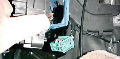
Remove the C3 (X3) connector from fuse block to isolate the high- speed LAN modules in two halves.
• Disconnect each module one at a time and bypass the module by using jumper wires to connect the high-speed LAN bus back together. Only use the correct test probe/ terminal when bypassing the module.
• Separate the bus into two halves by disconnecting the C3 (X3) connector from the back of the left instrument panel junction block. With the C3 (X3) connector removed, only the ECM, TCM, and BCM will be online with the scan tool. If there is communication with these modules, the concern is on the side of the bus that is disconnected.
Many high-speed LAN modules use small .64 series terminals and are often the main culprit for intermittent electrical concerns. When probing modules or inline connectors with .64 series terminals, be sure the correct .64 test probe is being used.
Questions? Please send us a note via our contact us. If you’d like to speak to one of our TAC agents, call the ACDelco Info-Line.
The Data Link Connector (DLC) allows a scan tool to communicate with the high-speed GMLAN (Local Area Network) serial data modules. The serial data is transmitted on two twisted wires that allow speeds up to 500 Kb/s. The twisted pair is terminated with two 120-ohm resistors – one is internal to the ECM and the other at the opposite end of the high-speed bus after the last module.
If a communication signal is lost, the software application will set a no communication U DTC (Diagnostic Trouble Code) against the respective control module. A loss of serial data DTC does not represent a failure of the module that the code is set in.
Always refer to the appropriate Service Information for the latest diagnostic information and procedures. The following diagnostic tips may help in locating the source of a loss of communication with a high-speed LAN module.
If the scan tool cannot communicate with any high-speed LAN modules, check for proper terminal drag at the DLC terminals 6 and 14 using test probe J-35616-14 or -2A. These terminals can become damaged from repeat probing and/or installing of the scan tool.
Probe terminals 6 and 14 using the proper test terminals.
Verify the high-speed LAN circuit integrity by measuring the resistance across DLC terminals 6 and 14 with a DVOM with the battery disconnected. A normal reading would be 60 ohms +/– 5 ohms. A reading less than 60 ohms would indicate the high-speed LAN bus is shorted together and a higher reading indicates high resistance/open in the high- speed LAN bus.
If the high-speed LAN circuit integrity is good and the scan tool still will not communicate with any high-speed LAN modules, there could be a module corrupting the high- speed LAN bus. Try these methods to isolate which module is causing the concern:
• Remove the battery feed fuse for each high-speed LAN module one at a time while monitoring the scan tool to see if communication returns with the other modules.
Remove the C3 (X3) connector from fuse block to isolate the high- speed LAN modules in two halves.
• Disconnect each module one at a time and bypass the module by using jumper wires to connect the high-speed LAN bus back together. Only use the correct test probe/ terminal when bypassing the module.
• Separate the bus into two halves by disconnecting the C3 (X3) connector from the back of the left instrument panel junction block. With the C3 (X3) connector removed, only the ECM, TCM, and BCM will be online with the scan tool. If there is communication with these modules, the concern is on the side of the bus that is disconnected.
Many high-speed LAN modules use small .64 series terminals and are often the main culprit for intermittent electrical concerns. When probing modules or inline connectors with .64 series terminals, be sure the correct .64 test probe is being used.
Questions? Please send us a note via our contact us. If you’d like to speak to one of our TAC agents, call the ACDelco Info-Line.